
The Design of the Bleriot Monoplane
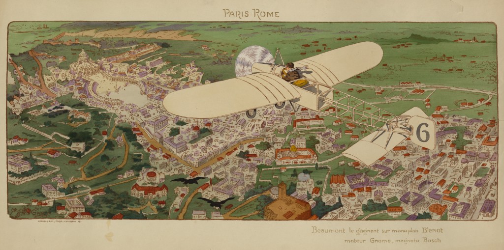
Lieutenant Jean Louis Conneau AKA Andre Beaumont In A Bleriot Airplane 1911 Paris Rome Race
[An Impression Of The Bleriot Monoplane By A. B. Rigby Republished from Cassier’s Magazine November 1909]
The first impression made on the majority of those who availed themselves of the op- portunity given for a close inspection of the Bleriot monoplane is that the machine looks extremely small. And herein lies its attractiveness.
On investigation, one is still further impressed with the fact that great progress has been made in the science of flight when a machine with a wing area of only ISH square feet, propelled by an engine developing only 20 horse-power, can be self-supporting and, at the same time, carry a driver, who need not necessarily be below the weight of an average man.
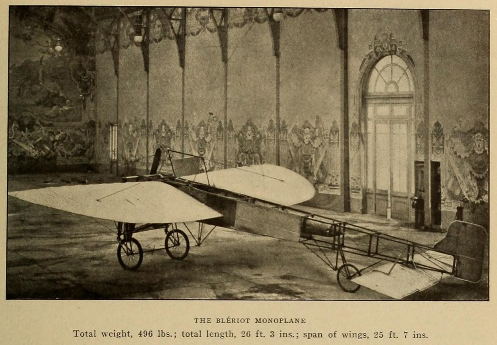
Bleriot Monoplane 1909 Cassier’s Magazine
On this machine M. Bleriot crossed the English Channel on Sunday, July 26, 1909, completing a distance of 31 miles in 43 minutes. During this flight be attained a speed of more than 40 miles an hour.
The following details give the approximate weights and measurements:
Total weight 496 pounds
Total length 26 ft. 3 ins.
Span of wings 25 ft. 7 ins.
Span of elevating planes 1 1 ft. 7 ins.
Superficial area of wings 150 yi sq. ft.
Length of blades 3 ft. 8 y 2 ins.
Engine 20-HP. “Anzani” (two blades, three cylinders, air cooled).
The details of this machine are worthy of careful notice. Starting at the propeller, one naturally wants to know why it is made of wood, this seems so fragile. Probably weight considerations decided the inventor in the choice of material.
Then in the engine we see a three-cylinder, air-cooled engine nicely made, but very much on the lines of the ordinary, every-day engine one sees on motor bicycles; no elaborate care seems to have been spent on reducing the weight (as far as outside appearances go), and the engine seems to be substantial and not particularly small for the horse- power it is said to develop.
There are one or two points which are open to criticism. First, the use of automatic inlet valves, which are certainly not as dependable as mechanically operated valves; secondly, the contact maker on the ignition system seemed to be exposed to the elements; and thirdly, the exhaust ports point directly towards the body of the machine and towards the driver, an arrangement which must be very unpleasant from the driver’s point of view, and might be dangerous, as they apparently are very close to the fabric of the wings.
The arrangement of the induction pipes, carburetor, petrol tank, etc., calls for no special comment, as they are installed in the simplest possible way; the only criticism likely to be made is that they appear to be entirely unprotected.
The engine and its accessories, including the propeller, are supported at the front end of a rectangular framework, which forms the body of the machine and which tapers away to the rear, ending up in a rudder very much resembling a fish’s tail.
Close to the rear end of the body frame is attached a pair of fixed fins, or planes, one on either side, standing out at right angles to the body frame in a horizontal plane. The ends of these fins, or planes, are movable, being pivoted in the centre, so that they can be deflected from the horizontal position by means of a crosspiece or tiller-head operated by two steel wires secured to the ends of the tiller-head. These planes are apparently used for elevating or depressing the machine during flight.
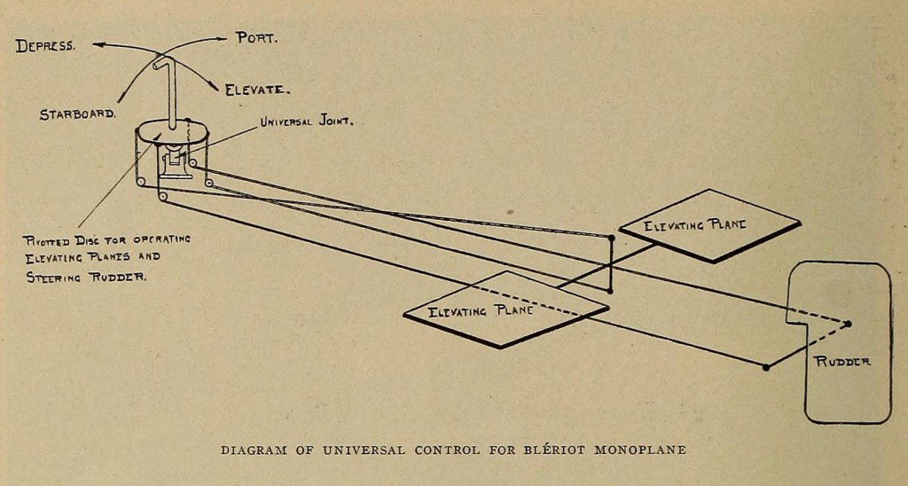
The fish-like tail is also pivoted and operated by a cross-arm, or tiller-head, and is apparently used only for turning the machine either to right or left during flight. Now we come to the device for operating the elevating planes, or rudder, which is neatness and simplicity itself, as are most of the details of this wonderful machine.
The four steel wires (two attached to the tiller-head operating the elevating planes and two attached to the tiller-head operating the rudder) are brought forward along the body frame and pass through guide-pulleys attached to a board secured horizontally to the underneath members of the body frame just in front of the driver. These pulleys are spaced so that the wires come up through the board at points equivalent to the corners of a square, the square being arranged so that the wires controlling the elevating planes come up at points in a line with the direction of flight and the two wires controlling the tail at points at right angles to the direction of flight. The four wires are firmly secured to a disc, which is shaped like a dish placed upside down, and having the wires attached to the edge. This dished disc is provided on the underneath side with a universal joint secured to the centre of the disc, and also secured to the board through which the controlling wires pass; and from the centre of the upper side of the disc a handle protrudes with a right-angled crook at the top, like a walking stick. The driver sits in a seat directly behind this controlling mechanism, with the control handle coming up between his legs.
Bleriot Monoplane 1909 Cassier’s Magazine
It will be at once seen how beautifully simple the control becomes — a movement of the control handle forward or backwards in the line of flight elevating or depressing the machine, whilst a movement to right or left across the line of flight turning the machine to left or right.
The disc operating the control wires being mounted on a universal joint allows a combined movement of the elevating planes and the steering rudder, and, no doubt, complicated evolutions could, with practice, be carried out with the greatest ease and with little effort on the part of the driver.
This single lever control is, undoubtedly, a very well thought-out piece of mechanism.
As to the body frame and lifting planes, or wings, the structure is composed principally of light ash scantling tied with steel wire and ribbon, very fragile, apparently, but extremely light. A noticeable point about the lifting planes, which are rigidly attached to the body frame, is their similarity in shape and construction to the wing of a bird, being thickened along the cutting edge, away to a thin edge at the rear. The framework of the lifting planes or wings has fabric on either side, leaving air space in between — a valuable asset, probably, in the event of the machine coming down into water, as the wing would certainly materially add to its floating powers.
The machine is provided with two wire-spoked wheels at the forward end, and one at the rear for starting and alighting, provided with rubber shock absorbers, so arranged as to allow considerable movement of the wheels on alighting — a very necessary precaution with so frail a structure.
The general impression created by a careful inspection is that the machine, as built, has a great many good points about it, from an engineering point of view, yet the general construction can only be accepted as experimental; and the framework is so extremely fragile that one wonders how alighting at any time is possible without causing serious damage.
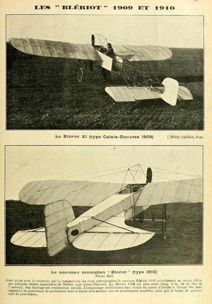
1909 and 1910 Bleriot Airplanes As Published In L’Aerophile Revue Technique Feb 15 1910
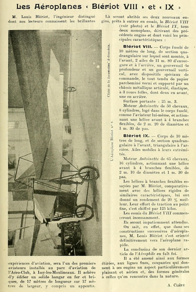
Bleriot Airplanes VIII And IX As Published In L’Aerophile Revue Technique Apr 15 1908
Bleriot Airplanes VII As Published In L’Aerophile Revue Technique 1907